Georgia Tech’s Hydraulics Lab studies environmental fluid dynamics across various STEM disciplines
A thin stream of water jets out of a loose link of PVC pipe and sprays onto the floor. “Is that okay?” someone asks, pointing to the miniature rupture.
Andy Udell, senior facilities manager for the School of Civil and Environmental Engineering (CEE), takes a look at the spillage and shrugs. “No. But that’s alright. You're supposed to have water on the floor in the hydraulics lab.”
As you walk into CEE’s Hydraulics Lab, nestled into the side of the Jesse W. Mason Building, you’re struck by its sheer amount of space – 14,000 square feet. The expansive ceilings frame a network of intersecting blue pipes. To the left is a massive tank, surrounded by various instructional equipment and a wall of old artifacts, historical curios transported from the previous lab space in the Old Civil Engineering building. To the right, the room is partitioned by wire fences, creating areas for whiteboards, workbenches, and flumes, one stretching to 14 feet wide.
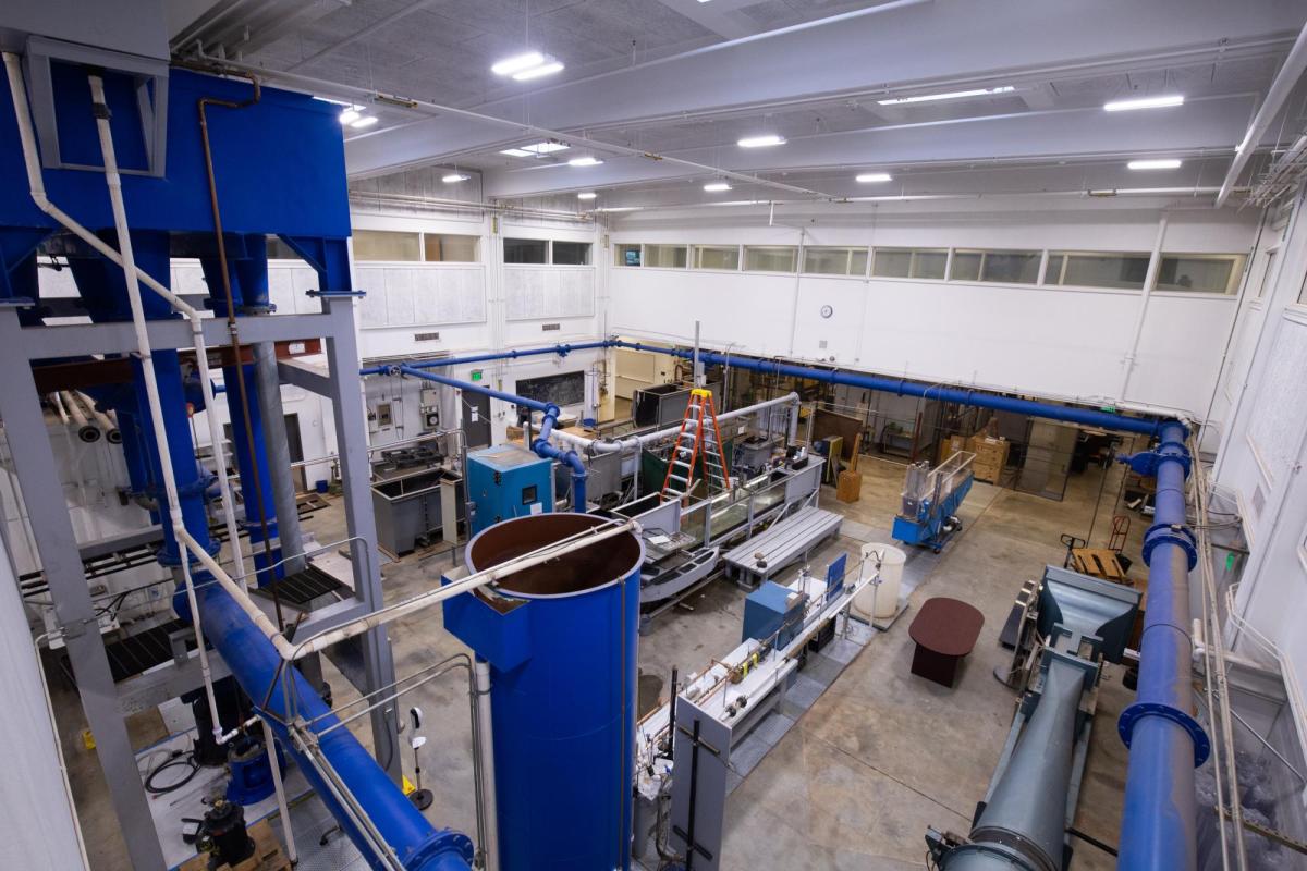
Underneath the carefully constructed research equipment and workbenches lies 20,000 gallons of water, most of which resides in a sump spanning the entire lab. The water flows into experiments through the overhead pipes and dumps into a subterranean cache that is connected to the blue tank towering over the lab’s inner workings. A platform of concrete flooring and lines of steel plates separates the lab from the water.
Udell has maintained the Hydraulics Lab since 1998, in addition to seven other spaces around campus.
“The Georgia Tech Hydraulics Lab is famous for the landmark historical research that’s been done here over the years,” said Udell. “There are several like it across the country, but this is one of the more well-equipped facilities of its kind.”
The History
The Mason Building was constructed in 1968 after CEE outgrew its previous facilities in the Old Civil Engineering Building overlooking Freshman Hill. Georgia Tech needed a lab space dedicated to research in environmental fluid dynamics, and so the Hydraulics Lab was built. While the lab focuses mostly on environmental issues, it is an interdisciplinary space. Students and faculty from mechanical engineering, biology, and many other schools across campus come to study and participate in the facility’s multifaceted research.
One of the first things students and faculty pass when entering the lab is its wall of artifacts. Towards the left is an old, green multimeter with many dials and buttons. A sideview cutaway of a vertical Francis turbine sits on one shelf. It was used for experiments focused on jet impact.
All the artifacts are encased in original mahogany display shelves, built by one of the lab coordinators in the Old Civil Engineering Building. With its prominent display of technological artifacts, the lab positions itself within Georgia Tech’s rich history of research and innovation.
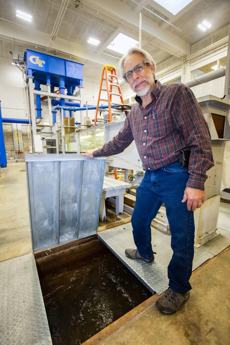
The underground sump spans the perimeter of the lab and collects water once it leaves the flumes
The Water
The Hydraulics Lab’s main feature is its steady supply of water. Fluid dynamics is primarily focused on the flow of liquids and gases, which can be modeled using water flow. The lab’s goal is to limit waste by using and recycling water as efficiently as possible.
The water used in experiments comes from the overhead tank, which is connected to each experiment through pipes. When the tank is activated, water flow rate can reach up to 9,000 gallons a minute (the same as 3,000 toilets flowing at once), an especially helpful feature for some of the large river models used in grant-funded environmental research in the facility.
After it flows through the equipment, the water is recycled back into the sump. It is eventually directed from a pump to the tank to be used again.
The Equipment
The seven flumes — deep, narrow channels — are the lab’s main pieces of equipment. They are constructed using metal and transparent plastic panes, which show water movement as it flows through the apparatus. Their sizes range from 15 feet long to 80 feet long, depending on the experiment.
For instance, one medium-sized flume is currently filled with rocks and sediment. It is used for some of the larger scale model experiments and holds a model of a spillway structure in the South Florida Water Management District. The spillway was designed to control water discharge flowing into a nearby riverbed.
Due to faulty plans, however, the district provided a research grant to Terry Sturm, a CEE professor emeritus, to re-evaluate the spillway design. Sturm’s lab built a model based on historical data and used the flume to reproduce the issues the district was facing. After running simulations with different headwater and tailwater conditions, the Georgia Tech team provided the district with potential solutions to fix their water overflow issues.
Several more of Sturm’s older projects are still set up around the Hydraulics Lab. The lab’s largest flume – 14 feet wide and 80 feet long – still holds the remnants of a Macon bridge site model from the professor’s research.
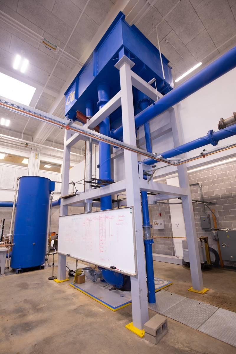
The overhead tank can store 20,000 gallons of water, dispensing it at a maximum velocity of 9,000 gallons per minute.
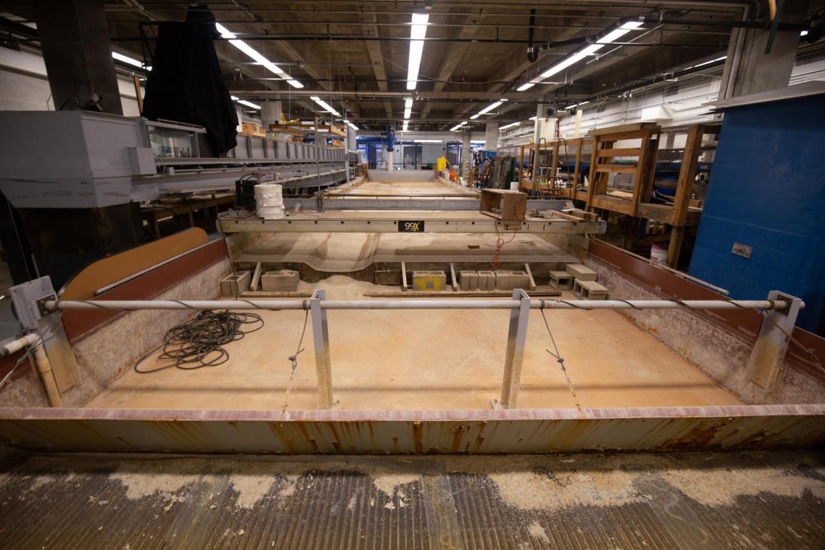
A lab flume containing the remains of a Macon bridge site model
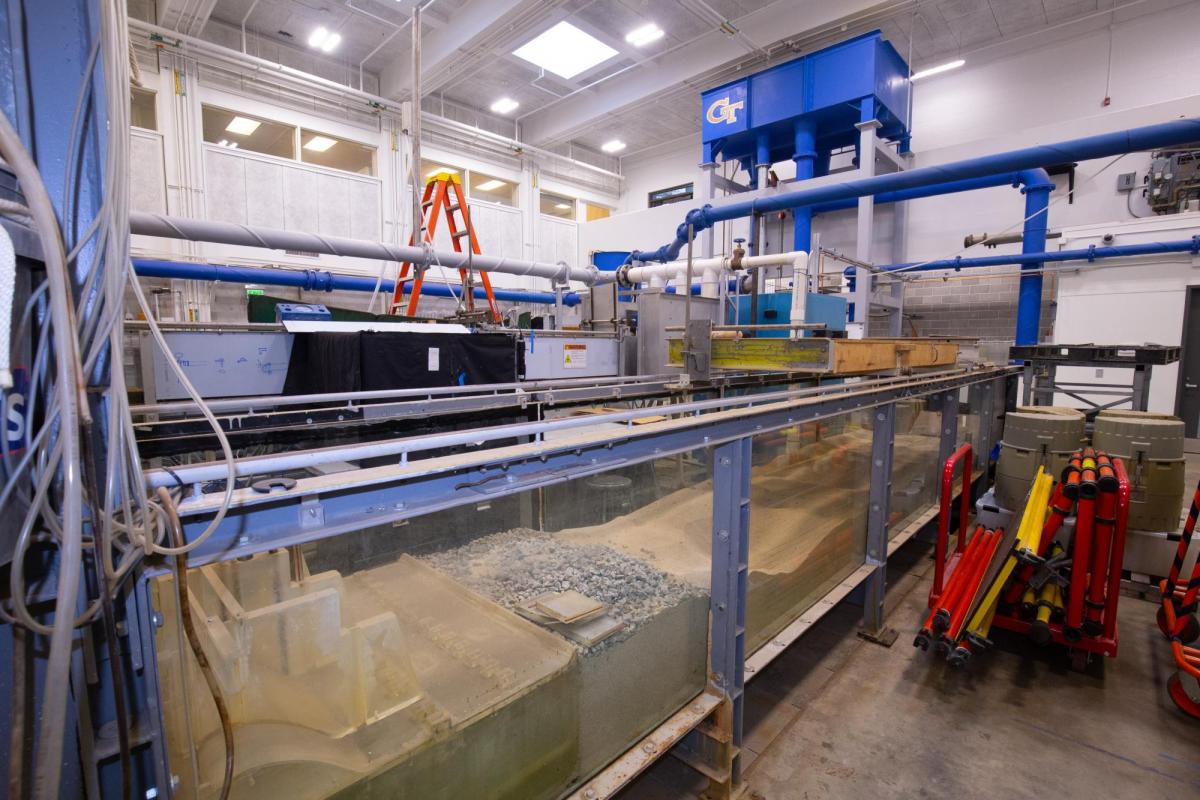
This flume contains a model of a spillway structure in the South Florida Water Management District
The Research
Much of the current Hydraulics Lab research occurs on the right side of the expansive facility, behind wire fence hallways partitioning different lab groups. One belongs to the team of Assistant Professor Chris Lai. He’s investigating the thermal fluid dynamics of glacial ice melts. According to Lai, roughly 60% of the observed sea level rise from the past two decades comes from polar ice melts. To accurately predict future global levels, the lab aims to first understand the unique way that freshwater glacial ice interacts with saline ocean water as it melts by simulating the current polar environment and measuring the rate of melt.
The lab’s set-up includes a large freezer to create simulated glacial ice, a transparent holding container to conduct the experiments, and a room with a high speed pulsed laser that is used to measure the fluid velocities of melted water, hence melt rates, via particle image velocimetry. The space is enclosed by walls of white aluminum panels, covered top to bottom in dry-erase marker calculations, which are mostly related to the details of the experiments.
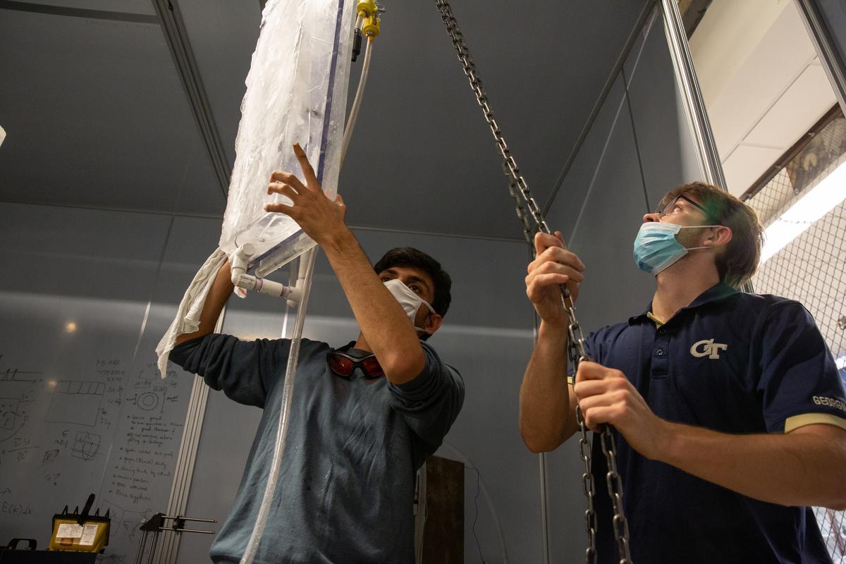
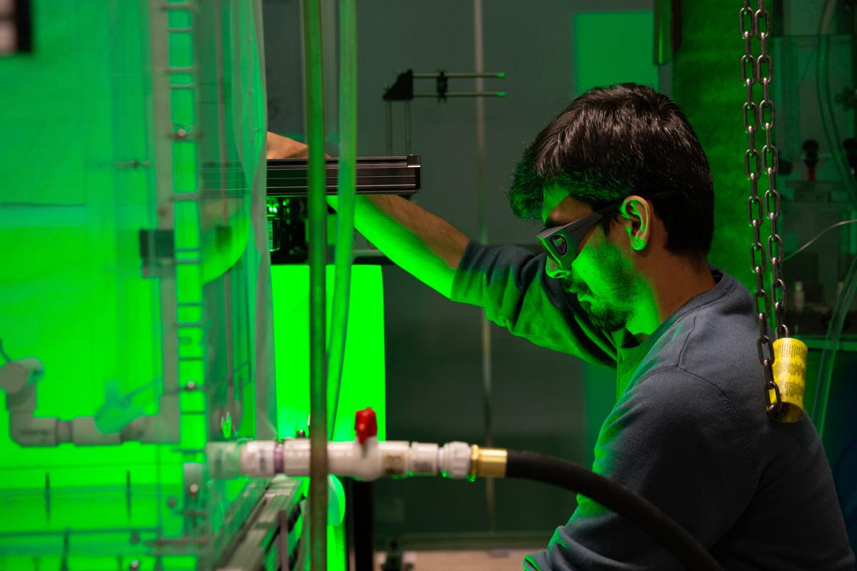
Lai’s lab also uses one of the medium-sized flumes to simulate the wind flow through a forest with applications in predicting forest fire scenarios. This can help determine how quickly fire spreads based on wind speed and different foliage densities. To accurately model a forest setting, the team printed 3D tree models with three-pronged fractal offshoots to act as branches and simulate tree canopies.
Since air and water move in the same way, measurements of water flow through the model forest can accurately predict the movement of air through a real forest during a large-scale fire. The team uses particle image velocimetry to measure the fluid velocity at different areas of the forest. Lai emphasizes the importance of studying flow through different parts of the forest rather than looking at the forest as one unchanging whole.
“Our experiment looks at the flow at the top level of the forest, in the canopy, and compares that to the flow at the ground level,” said Lai. “These are the nuances you have to investigate before moving on to bigger questions, such as how quickly the fire spreads overall or how much carbon dioxide will be released into the forest canopy.”
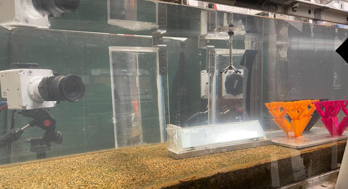
Lai's lab uses a flume for their forest fire simulation
Flumes and lasers aren’t the only research equipment used in the lab. Angelica Connor, a graduate research assistant in CEE School Chair Don Webster’s lab, uses a 3D imaging setup to observe the movement and flow fields around free-swimming zooplankton in ocean water.
Connor uses a small, climate-controlled room off the main Hydraulics Lab space to create her imaging apparatus – cameras hung at different angles, all pointed towards a small hexagonal tank containing the zooplankton. This setup can take a series of 2D images from different angles that allow Connor to calculate the 3D movement of water particles and zooplankton over a certain period of time. She also uses a high-powered laser for particle image velocimetry measurements, and she can create graphs visualizing data such as how fast the zooplankton swim and the flow fields that form around them.
Connor has recently been experimenting with tiny zooplankton robots that can move similarly to the underwater creatures using magnetic fields set up around the observation tank. Although she is studying in the George W. Woodruff School of Mechanical Engineering, Connor used her understanding of machines to create her 3D imaging setup and the robot zooplankton.
Webster’s main lab, located in the far-left corner of the Hydraulics Lab, also studies 2D zooplankton flow fields and copepod-turbulence interactions using a Berg vortex.
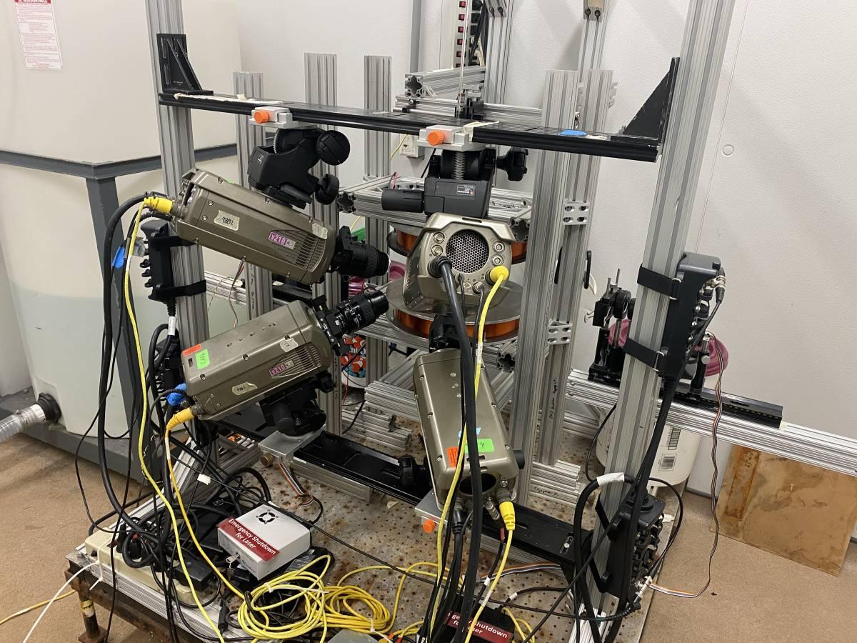
Connor's 3D camera apparatus
The Donovan Undergraduate Teaching Lab
The lab is not only used for research. Much of the left side of the facility focuses on undergraduate instruction through CEE’s Donovan Undergraduate Teaching Lab. Upper-level CEE classes include instruction about different aspects of fluid flow through demonstrations such as red oil and hydraulic jump experiments. Students can use various metering devices like the venturi and orifice meters to measure flow.
“There’s lots of research happening in the lab not just to advance knowledge, but to advance instruction and teaching techniques,” said Professor Hermann Fritz. His research on tsunamis and other natural disasters takes place mostly in the tsunami wave basin at Oregon State University’s Natural Hazards Engineering Research Infrastructure (NHERI) facility, but he also teaches CEE 4200, Hydraulic Engineering, which has a mandatory lab component in the Hydraulics Lab.
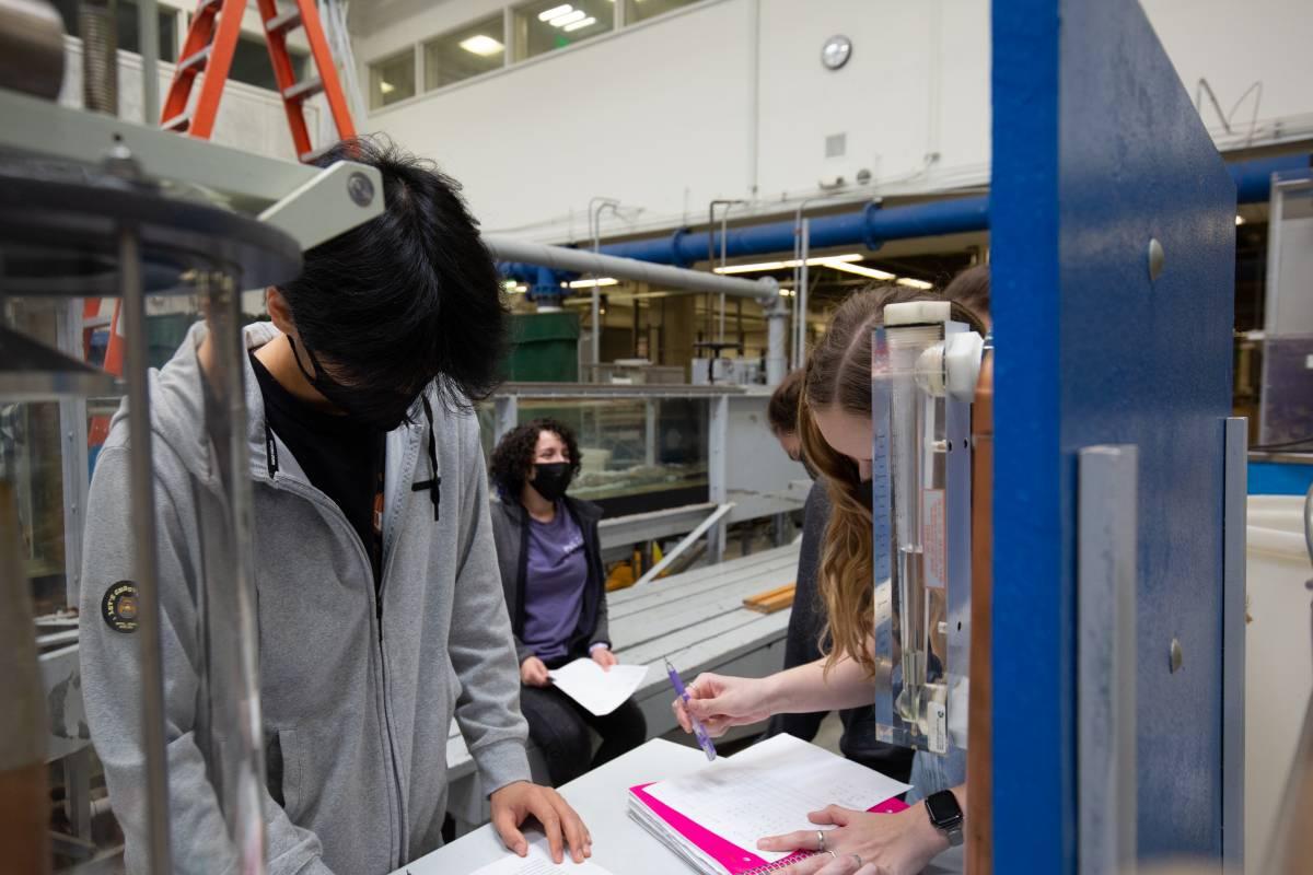
Undergraduate students learn about the Hydraulics Lab space in classes such as CEE 4200
Fritz has been working to incorporate newer technologies into CEE’s lab coursework. Recently, he updated the measurement techniques used in the hydraulic jump experiment demonstration from more classic methods to a newer, low-cost version of particle image velocimetry. Instead of using lasers, Fritz uses a fiber optic light sheet to illuminate the bubbles in the water and capture the flow velocity in different flume locations.
“Classical methods of measurement are still necessary to know when doing fieldwork, but it’s helpful for the students to catch a glimpse into spatial and temporal or resolved velocity water flow measurements, which is something they wouldn’t normally get to do,” said Fritz.
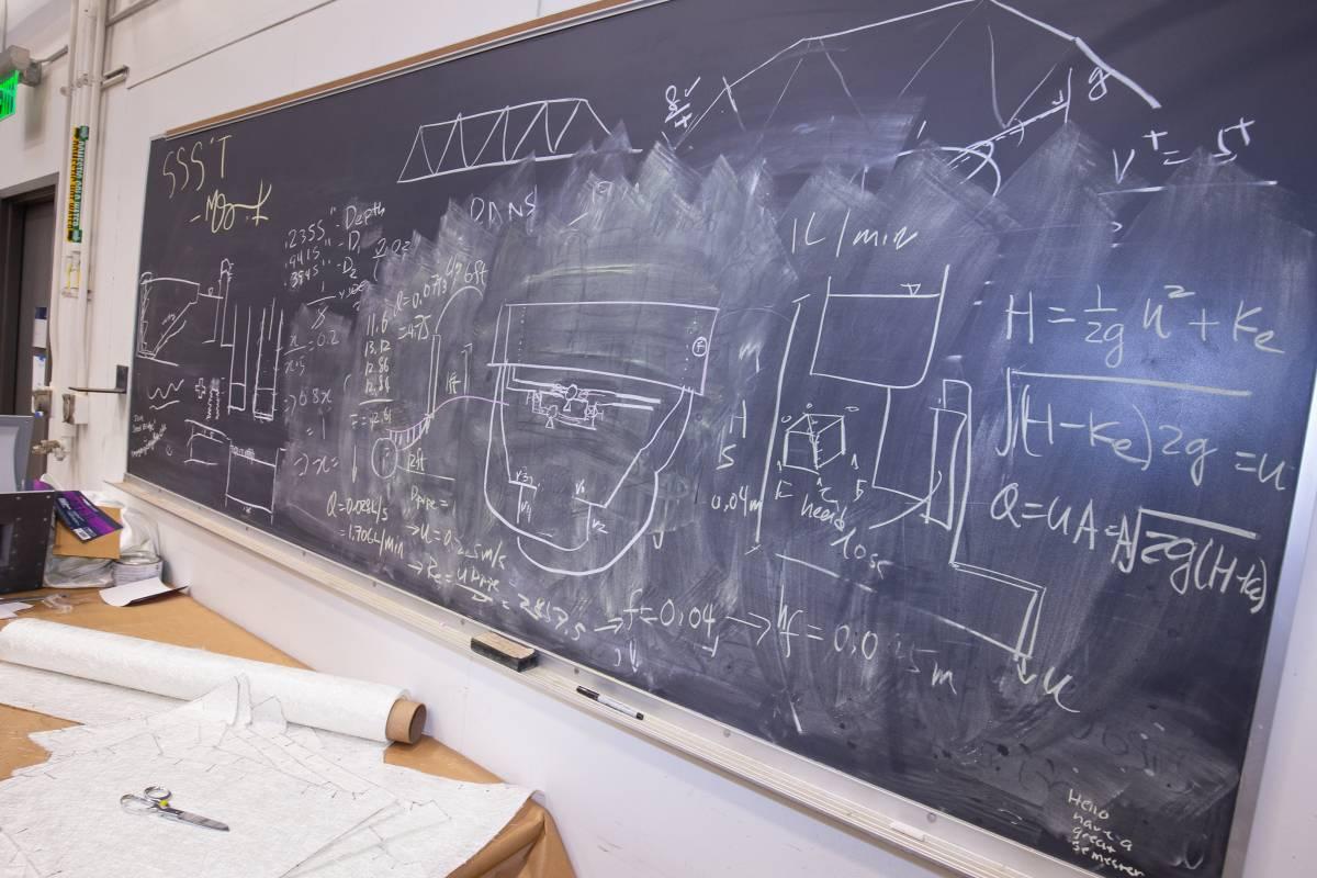
Lai and Udell's calculations for a shallow water basin upgrade